Smart speed bump for emergency vehicles
infrastructure product

The image above is from our technical review, where we demonstrated a car driving over our system (and it was also the first snow!)
Overview
Roles: Technical Sub-team Lead, Mechanical Design, Material Procurement
Skills: User Interviews, CAD (SolidWorks), Mechanism Selection, Material Selection, Machining
Time: September - December 2018
Team: 19 (MechE, CompSci)
Developed as part of 2.009, senior capstone for mechanical engineering. Although all members of the team contributed to some parts of the system such as determining the lifting mechanism, I was specifically in charge of leading a task force of 5 members to develop the active surface (the plates that attached to the lifting mechanism to form the bump and the rubber cover).
The Problem
Cities desire to regulate traffic while not interfering with the ability for first responders to quickly and comfortably transport patients. Speed bumps assist in traffic regulation (for example, near schools), but can cause jostling of patients during transportation, such that emergency responders often avoid routes with speed bumps, even if they are longer. In addition, city planners sometimes cannot add the extent of traffic regulation actually needed to mitigate these concerns.
Stakeholders Interviewed:
EMS - Watertown Fire Department, MIT EMS, Paramedic (Jacksonville, FL), Law Enforcement Officer (San Angelo, TX)
City Planners - Austin, TX; Seattle, WA; Bellevue, WA; Eugene, OR; Portland, OR; Richmond, VA; Washington D.C.
Traffic Engineers - Delaware, Florida, Michigan, Montana, Nebraska, North Dakota, New Hampshire, Utah, Washington Depts. of Transportation
Snow Plow Operator - Cambridge Dept. of Public Works
In order to balance the goals of both EMS and traffic regulation, we developed a dynamic speed bump that could be signaled to flatten by emergency responders (and in cities like Cambridge, during snow plows as well)
The Process
There were several parts to the system that we had to consider:
-
Detection: The system needed to sense that an emergency service was arriving and initate the system response.
This part of the system was based off of existing systems for traffic signal preemption. In our case, the electronics and sensing system (radio receiver) were integrated within the BUMP sign that was located near the speed bump. For our prototype, we powered the system as if it were connected to the electrical grid, although we considered cases where it could be solar or battery-powered. The system was designed so that EMS could initiate the signal from 1500 ft away, giving the speed bump approximately 20 seconds to collapse for a vehicle traveling 50 mph.
-
Signaling: There needed to be an indication of the speed bump’s status (up, down, or in-motion) to anyone on the road.
LEDs on the BUMP sign were programmed to indicate the state of the bump. The default state was set to be “up” as if it was a normal speed bump (no LEDs). When signaled to flatten, the LEDs would flash green. In the “down” state, the LEDs on the top and bottom of the sign would turn solid green. Finally, any error or system failure would be indicated with the LEDs on the left and right sides turning red. Because it was important that EMS would slow down in the case the speed bump was not operational (could not collapse), the LEDs were chosen to operate with the assumption of an “up” state and a clear indication in the case of a successful collapse.
-
Collapsing: The bump needed to flatten in a required amount of time.
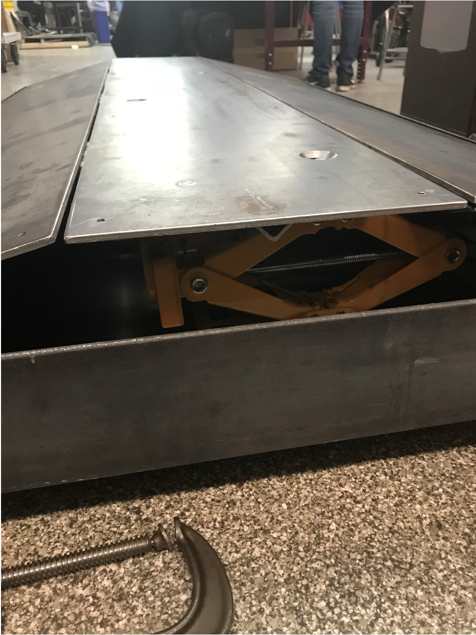
For this part, the critical part was that the speed bump could both lift and sustain a minimum load (the weight of the largest vehicle that would be allowed on the street). After considering lifting mechanisms including a pneumatic bladder, air springs, and ratchets, we decided to use 4 3-ton electric scissor jacks for our prototype, as it allowed the bump to flatten in 10 seconds and could hold up a car. These were attached to a base that would be placed in an excavation in the street. The scissor jacks were then attached to a hinged steel plate assembly that would form the bump or flattened shape.
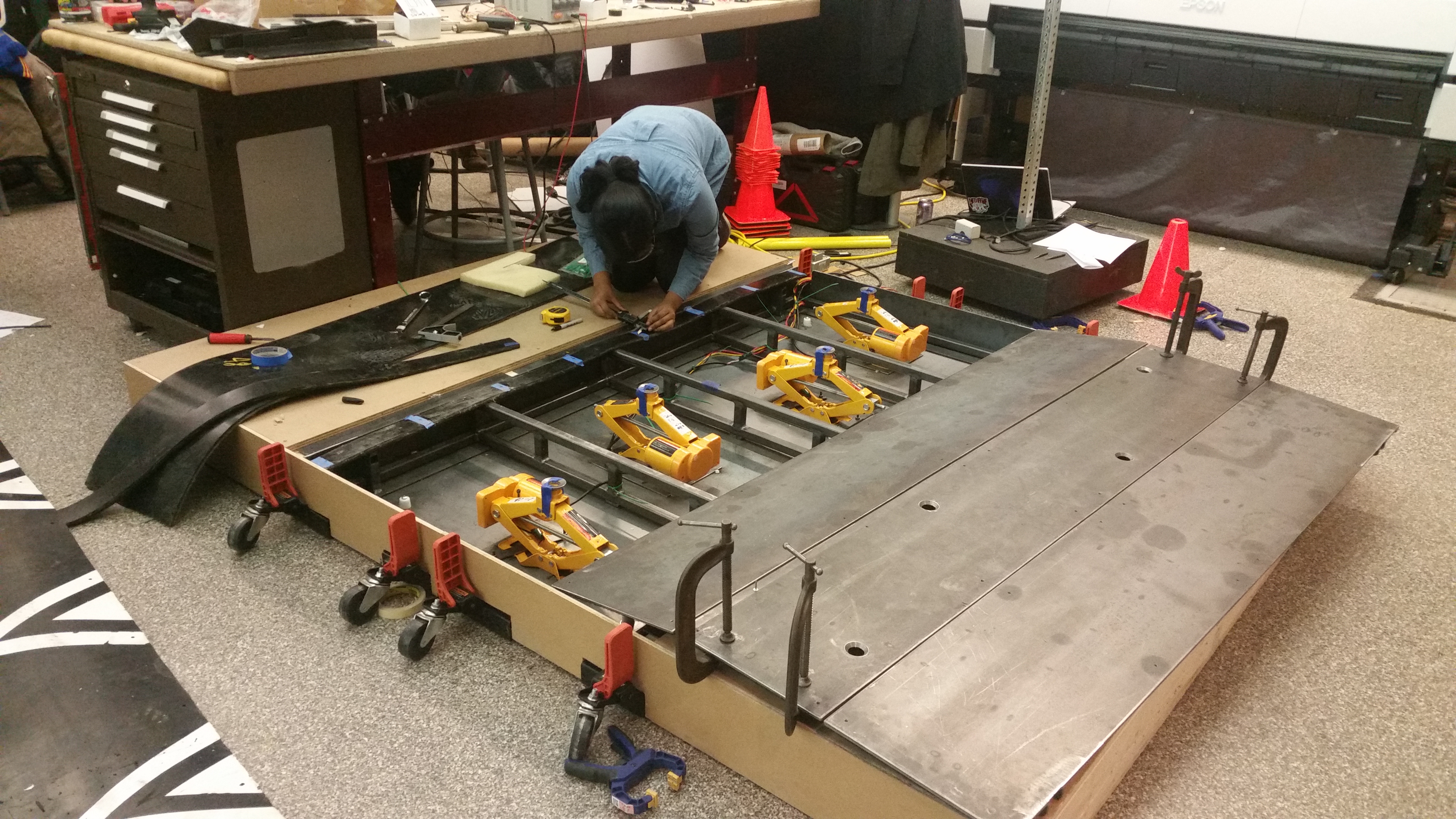
Here’s me working on the final assembly in our makeshift “excavated” road and the speed bump in its almost fully assembled form..
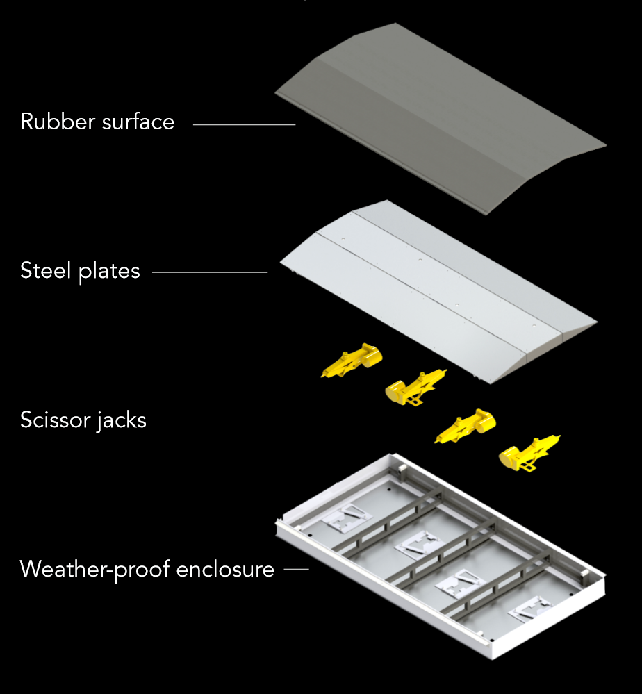
Finally, the speed bump was covered with a protective rubber outer surface that could not only be painted with the traditional speed bump markings, but would also protective the surface from rust and protect the internal mechanisms from weather and corrosion. An exploded view of the entire assembly is shown below.
The Result
The final prototype of the entire system could successfully be signaled to lower, driven over, and lifted back up with corresponding LEDs on the sign. The photo below shows the final prototype.
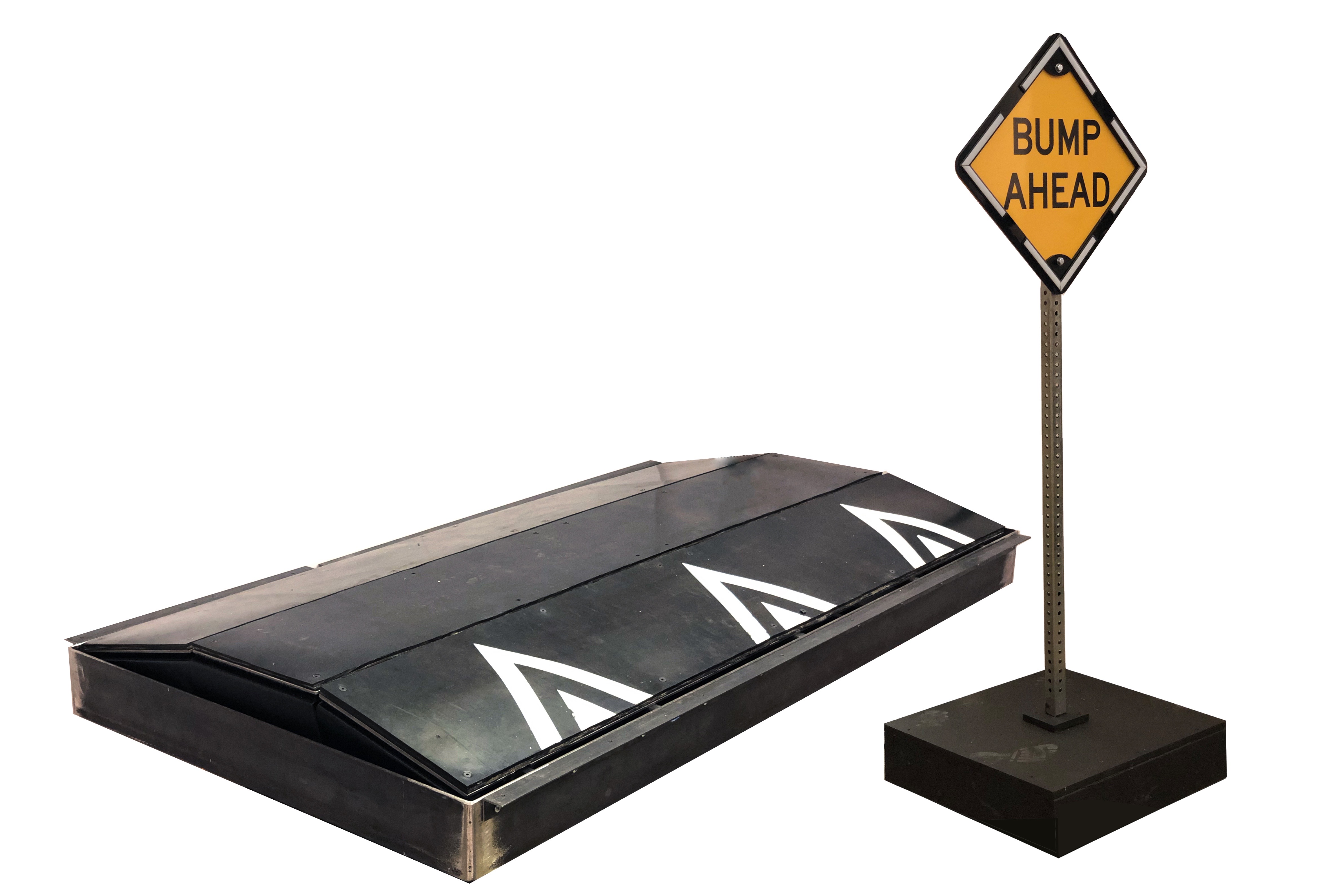
In addition, we presented a demonstration of the system in front of over 1000 people:
Reflection
This was the first time I worked on a team of this size and it was a great exercise in figuring out how to divide into sub-teams while ensuring the subsystems could be integrated in the end. An important part of the process for this project was talking to and learning from many different stakeholders. Since the problem here is at a larger scale than a typical consumer product, a device such as Sentry would be facing many more types of stakeholders than anything I had worked on in the past. In addition, working on an infrastructure-related product allowed me to get a system-level view of design, thinking about not only the technical aspects, but also service-related aspects, such as how maintenance would work or how any failures would be handled.